Project Stories10 min read9 October 2026
Anatomy of an Autonomous Robot: From Sensors to Decisions and Actuation
An autonomous robot is an integrated system that senses its surroundings, estimates its state, plans actions, and executes movements without requiring continuous human control. This article explores the theory behind autonomous robotics, including sensor fusion, localization, motion planning, control systems, embedded computing, and the feedback loops that enable robots to operate in dynamic environments.
By Anonymous Writer
1. What makes a robot autonomous?
An autonomous robot is a machine capable of performing tasks by interpreting sensor data, making decisions, and controlling its own actions. Unlike a remotely controlled robot, an autonomous system uses onboard software and feedback mechanisms to determine what to do next.
The foundation of autonomy is the interaction between three essential capabilities:
- Perception: Understanding the environment through sensors such as cameras, LiDAR, radar, and ultrasonic sensors.
- Decision-making: Selecting an appropriate action based on the robot's objectives, estimated state, and environmental conditions.
- Control: Translating the selected action into motor commands while accounting for physical constraints and disturbances.
A robot that only follows a predefined sequence of motor commands is automated, but it is not necessarily autonomous. Meaningful autonomy requires some ability to respond to changing conditions.
2. The architecture of an autonomous robot
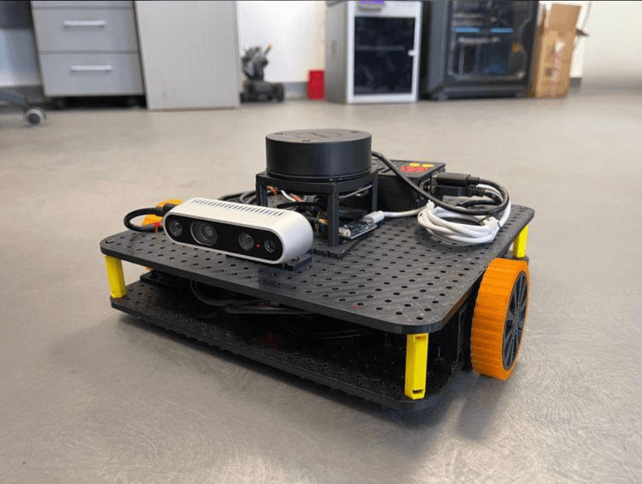
A practical autonomous mobile robot typically contains six interconnected subsystems.
Sensors
Camera · LiDAR · IMU · Encoders
Perception
Objects · Obstacles · Features
State Estimation
Position · Orientation · Velocity
Planning and Decision-Making
Goal selection · Path · Trajectory
Control System
Velocity commands · Motor targets
Actuators and Robot Motion
Motors · Wheels · Steering
Feedback loop
New sensor measurements update the robot's state and trigger replanning when necessary.
These subsystems do not operate independently. For example, a localization error can produce an incorrect path, while poor motor control can prevent the robot from following an otherwise valid trajectory.
3. Perception and sensor fusion
An autonomous robot needs a useful representation of its surroundings. Different sensors provide different information, and no individual sensor is reliable in every situation.
- Cameras: Provide color, texture, object appearance, and visual features.
- LiDAR: Measures distances to surrounding surfaces and supports geometric mapping.
- IMUs: Measure angular velocity and specific force, helping estimate motion and orientation.
- Wheel encoders: Measure wheel rotation and provide an estimate of traveled distance.
- GNSS receivers: Provide global position estimates when suitable satellite signals are available.
Sensor fusion combines these measurements to obtain a more reliable estimate of the robot's state.
This is one of the mathematical foundations of localization and navigation. More advanced systems may use error-state Kalman filters, factor graphs, visual-inertial odometry, or LiDAR-inertial estimation.
4. Localization and SLAM
Localization answers the question: Where is the robot?
Mapping answers: What does the environment look like?
Simultaneous Localization and Mapping (SLAM) estimates the robot's trajectory while constructing a map of an initially unknown environment. It is especially important for robots operating indoors, underground, or in environments where GNSS is unavailable.
A typical SLAM pipeline includes:
1. Acquire synchronized sensor measurements.
2. Extract visual features or geometric information from LiDAR scans.
3. Estimate motion between successive observations.
4. Identify previously observed locations through loop closure or place recognition.
5. Optimize the estimated trajectory and map to reduce accumulated error.
SLAM is not a single algorithm. Visual SLAM, LiDAR SLAM, and visual-inertial SLAM use different sensing approaches and assumptions. Their performance depends on factors such as environmental texture, geometric structure, motion, sensor quality, and computational resources.
5. Path planning and obstacle avoidance
Once the robot has a position estimate and a representation of its environment, it needs to determine how to reach a goal.
Path planning and trajectory planning are related but distinct:
- Global path planning finds a route through the environment, often using a map.
- Local planning responds to nearby obstacles and changing conditions.
- Trajectory generation adds timing, velocity, and acceleration constraints.
- Obstacle avoidance modifies or rejects unsafe motions before execution.
Algorithms such as A* and D* Lite are used for graph-based navigation, while RRT and RRT* can search complex configuration spaces. Local navigation may use the Dynamic Window Approach or Model Predictive Control, depending on the platform and requirements.
A geometrically valid path is not automatically executable. The robot must respect its turning radius, acceleration limits, braking distance, and dynamic capabilities.
6. Feedback control: making the robot follow its plan
A planned path specifies where the robot should travel. The control system determines how to move toward that path despite disturbances and modeling errors.
For example, a wheel-speed controller compares the target wheel speed with the encoder-measured speed and adjusts the motor command to reduce the error.
More advanced autonomous systems may use:
- LQR: Optimizes feedback for a linearized system with a defined cost function.
- Model Predictive Control: Predicts future system behavior and optimizes control actions over a moving horizon.
- Adaptive control: Adjusts control behavior when system parameters change.
- Robust control: Accounts for uncertainty and disturbances within a specified design framework.
The appropriate method depends on the robot's dynamics, computing budget, required performance, and operating environment.
7. Embedded computing and ROS 2
The algorithms must execute on real hardware. A typical autonomous platform divides computation between a microcontroller and a higher-performance computer.
Component | Typical responsibility
Microcontroller | Motor control, encoder counting, low-level I/O
Single-board computer | Navigation, perception, state estimation
Motor driver | Supplies controlled electrical power to motors
Communication interface | Exchanges commands and sensor data
Safety controller or circuitry | Implements required stop and fault responses
ROS 2 can connect these components through nodes, topics, services, and actions. Its middleware and Quality of Service settings help systems exchange data, but they do not automatically guarantee hard real-time behavior or functional safety.
Timing matters: stale sensor data, delayed commands, dropped messages, or overloaded processors can degrade autonomy even when the underlying algorithms are mathematically sound.
8. How to validate an autonomous robot
A successful demonstration is not sufficient evidence of reliable autonomy. Engineers should test the system under repeatable conditions and measure performance.
Useful metrics include:
- Localization error: Difference between estimated and reference position.
- Navigation success rate: Percentage of trials reaching the goal safely.
- Path efficiency: Comparison between the traveled route and an appropriate reference path.
- Obstacle clearance: Minimum distance from obstacles during motion.
- Control tracking error: Difference between commanded and measured motion.
- Computational latency: Time between receiving data and producing a usable result.
- Recovery rate: Ability to resume operation after a defined fault or navigation failure.
Testing should progress from individual software components to simulation, hardware-in-the-loop testing, and controlled physical trials. Safety constraints should be established before allowing the robot to operate around people.
9. Conclusion
Building an autonomous robot requires much more than connecting sensors to a controller or implementing an AI model. It involves integrating physical modeling, perception, state estimation, planning, feedback control, embedded computing, and systematic validation.
The central engineering challenge is ensuring that every subsystem works together reliably under uncertainty. A robot becomes practically autonomous when it can repeatedly sense, estimate, plan, act, and recover from unexpected conditions within the limits of its design.
This is the level of technical depth I'll aim for in your future robotics blogs: explanatory paragraphs, structured points, relevant equations, engineering diagrams, implementation details, and evidence-based analysis.